
Architects and designers often need to know how a design will be incorporated into its real-life location, while clients and “non-architects” turn to photorealistic visuals (images, videos and more) for a deeper, more visceral understanding of the project and the architect’s intentions.
While working in Lumion, features such as OpenStreetMap (OSM) and satellite ground planes can provide some context for your design. They are suitable options for quickly building urban or rural environments relevant to your project’s location, but they’re also limited.
For instance, OSM only provides rough building shapes, rendered white, and the satellite maps are flat, often outdated, and the resolution is too low for client visualization.

NYC skyline with context provided by OpenStreetMap, rendered in Lumion 8.3.
This all got me thinking — there has to be a better way to improve fast context-building without having to sacrifice photorealism. I investigated several options, starting with Google Maps and Google Earth SDKs, but these services do not allow their data to be used outside the scope of Google Maps and Google Earth, such as for architectural visualization.
One solution is to create a 3D model of the environment using a series of photographs taken by a drone. This technique is sometimes used at construction sites to monitor progress, but it is not yet widely used for architecture design and visualization.
To test its viability, we used a drone-to-3D workflow for several real-life design projects. From our experiences, we derived a workflow simple enough to be used by architects (and not only 3D specialists). Using a modern drone and the software RealityCapture, it is now possible to capture an area of 300x300m and create a textured 3D model of sufficient quality for presenting a realistic background for your Lumion visualization.
Workflow Summary
This summary is a condensed version. Click here for the full drone-to-3D workflow story (PDF).
Step 1: Buy a Drone.

10-inch tablet and tablet holder next to the DJI Mavic Air.
Drones are getting cheaper, smaller and increasingly powerful by the minute. For this workflow, I used the DJI Mavic Air. It costs $800, weighs less than half a kilo and it can fly for 20 minutes on one battery. The DJI Mavic Air can also cover a distance of 10km and make 4K video and 4000×3000 images with good resolution. This is adequate for our purpose of creating 3D environments as a backdrop for architecture design or visualization.
Also, I’d recommend that you buy some extra drone batteries and, if needed, a 10-inch Android tablet.
Step 2: Capture Drone Images.
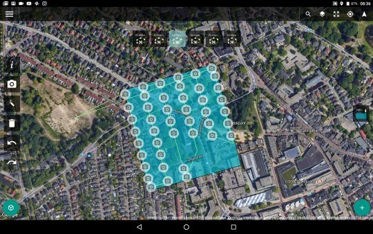
Using a special app on your tablet for controlling a drone, e.g., Drone Harmony, the second step is to capture images around the area of interest.
The Drone Harmony app lets you draw the area of interest on a map, and then it calculates the flight path of the drone, capturing images automatically with a 60% overlap from the previous shot. This overlap is needed for automatic 3D model construction.
10-inch tablet and tablet holder next to the DJI Mavic Air.
Do five runs of the same flight path above the desired area, but make sure you assign a different camera angle for each flight. For instance, you can fly the first run with the camera pointed down and the other four runs with the camera tilted at 45 degrees. Each run takes 7 to 15 minutes, so the entire flying will take about 1 to 1.5 hours overall.
Step 3: Enter images into RealityCapture (RC).
While there are many different software programs for compiling drone images into a 3D model, I found RealityCapture as the best option. RealityCapture automatically aligns all of the images and then it creates a 3D model, adds textures and inspects the model’s quality. This literally takes a few minutes of manual work, and a few hours at most of background processing by the RealityCapture software.
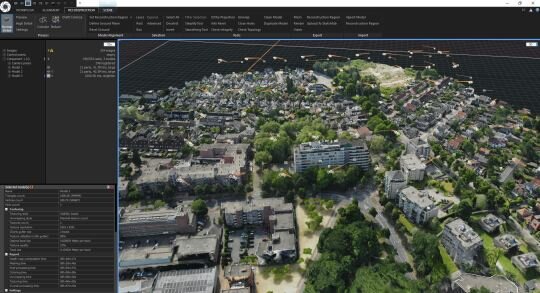
Constructed 3D model after RC aligned and processed the images from your drone flights.
Step 4: Cut out the lesser detailed areas and unwanted objects.
If the quality of the model is OK, the next step is to cut out the lesser detailed areas and unwanted objects, and then simplify the 3D model to a smaller model. Depending on the model’s size and complexity, this can be anything between 30K and 1M triangles.

Cut out a specific area where you will insert your CAD building or spaces.
Texture the model again and export it in an FBX format. Cutting and simplifying the model takes between 20 minutes and one hour.
Step 5: Import the model into Lumion.
After importing the 3D drone model into Lumion, you can dress it up with trees, cars, people, furniture, etc. You can also import your design from SketchUp or your CAD/BIM program (Revit, 3ds Max, AutoCAD, Rhino, etc) on a separate layer. Make renders and animations.
This typically takes anywhere between 15 minutes and several hours.
If you want the full story, with detailed information and tons of great images and videos, check out the full Drone-to-3D workflow (PDF).
Testing the Workflow on Real-Life Projects
I used this workflow for several projects. One is a test project of a beach and dune area featuring an existing Lumion example house. The following two are commercial design projects from local architects. These are briefly described in the next sections.
Beach and Dune Area
Test project. Existing Lumion beach bungalow added to a 500x500m captured beach area near The Hague, The Netherlands.
Private house design on a small island in a new residential area near Rotterdam, The Netherlands.
Architect: Studio Aaan.
From the architect: “The house is located on a private island in a new urban development close to the city of Rotterdam. The house is oriented towards the new park located on the next island southwards. In order to be able to enjoy the views, the living areas are projected above the surrounding dike levels and the sleeping areas are located below. The lower floor is half sunk into the island and is organized around two patios. As a structuring design principle, the roof consists of expressive wooden beams in a dense pattern. The beams create a canopy on the south facade as well as a characteristic interior ceiling.”
Feedback from the architect, Hilbrand Wanders, of Studio Aaan: “For any architecture project, but especially a private, freestanding housing project, the interaction of the building with its surroundings is crucial. We want to study the project as an architectural object on its location, but also want to consider how the surroundings are experienced from the interiors. Only once a house is finished and the owners move in, one can precisely see how certain trees are creating shadows in the house, what objects in the surroundings are blocking views from a certain position, or how window openings are positioned relative to window openings of the surrounding buildings. These aspects are highly influential on the living qualities and are difficult and too time-consuming to model by hand completely early in the design process. It is very interesting for a designer to consider the correct 3D environment from the first moment on, to test the first design-ideas within a correct 3D surroundings, but also to communicate these to a client in a very clear and tempting format. In the case of this project, the fact that the views on the site were blocked by surrounding dikes, were the reason to place the living rooms on the first floor. All other design steps (bedrooms around patios in souterrain, the stepped garden wrapped around the house) were consequential to this notion.”
Westpoint Apeldoorn Project
Refurbishment of an existing office building into 98 apartments, each with a balcony, in Apeldoorn, The Netherlands.
Nowadays, AOMA also including drone technology to all of our clients depending on needs and requirement. This including pre-construction (consultation stage), during and after construction.
Source : Lumion